Sunday, September 10, 2017

Cheap Wireless Microphone Systems

In the past, we had little choice but to use units from Shure, Sennheiser, AKG etc. if we wanted to use a wireless microphone system. Today these companies make very advanced wireless systems, even digital and encrypted systems. The cost of these sysems can go up to 6000€ for a 2 channel system. Although you can get cheaper models from same manufacturers, usually these models have restrictions on number of channels which can be used etc. These high prices are not surprising, since these companies have to divert most of their profits towards advertising and distribution. If a product is found in every store and its name is mentioned everywhere, people tend to associate with it easier. It is normal behavior to be weary of a product which you never heard of.

But... can we meet in the middle and get reasonable amount of features for a reasonable price? I will focus on units which can be found at AliExpress site. Today, it is possible to even find cheap units with digital transmission and rudimentary encryption at AliExpress.

While no doubt that you may get the best audio quality with a 6000€ unit (3000€/channel). Do you need to pay that amount if you can get a 300€ unit (75€/channel) which does the task you require?

In the final unit I chose, I couldn't find any audio artifacts while in operation. I showed the unit to few musician friends and they seem to think that it sounds fine also. This is never the less not a very scientific method, but if you can't hear the difference I am not sure if it is worth paying so much.

Unit Selection Highlights

There are so many models and brands, they all promise to be the best. How to choose?

Frequency Range

First of all, you must filter your choices by frequency. Most units sold on AliExpress have frequency settings which are totally unacceptable. The used frequencies are not in the free range in Europe, North America or even in China. I have discussed this issue with some sellers and learned that we can blame India for this. Apparently Indians want it this way, although I found out that those frequencies are not even the allocated wireless microphone frequencies in India. Never the less, you must complain to unit producer if you find a nice unit you want is in wrong frequency. This way, eventually they may start producing units in legal frequencies.

For example, currently in Finland the following frequency ranges are available for microphones:
174–230 MHz (TV-VHF) No licence required as from 1 January 2017
470–694 MHz (TV-UHF) No licence required as from 1 January 2017
823-832 MHz No licence required
863-865 MHz No licence required
1785–1804.8 MHz (UHF) No licence required

One important thing to mention is that it is not enough to operate a device in this range. Another restriction is that the user must NOT be able to set the device to any frequency outside these ranges. Otherwise device would require license or may be illegal to operate.

So, we already filtered out a bunch of systems.

User Manuals

I found out that user manuals give so much better feel of a system than just looking at its photos. This may not be same feeling for you. Also most sellers seem to say "it is easy to use, no need for manual". But the features and capabilities of the system give me an understanding of how much attention to detail was given and how advanced the system is. One other thing is that on AliExpress most sellers copy/paste specifications of systems. You get to the bottom of it by receiving manuals. Another thing is that the sellers tell whatever to sell you the device. Manuals usually give more truthful information about the operation of the device.

Beltpacks 3.5mm or Mini-XLR or With Volume Control

This mostly interests beltpacks. There seem to be two different types of beltpack connectors used in these systems.3.5mm screw locking or mini-xlr. While the mini-xlr may seem more advanced, all the chinese units use only pins 1 and 3 in these units. In addition, some units have the mini-xlr port connected upside down! meaning you get signal in pin 1 and ground in pin 3. If you choose an XLR beltpack system then you would need to make sure to ask the seller that the pins are not reversed. Otherwise this may effect microphone performance.

On the other hand, Chinese sellers will NOT recommend you 3.5mm units if you want to use instruments with them. The reason is not because these units do not work well with instruments, but it is simply difficult to produce cables for instruments with these units. The chinese 3.5mm screw lock solder plugs are very difficult to work with due to small soldering area on the connector.

The 3.5mm version beltpacks use mono jacks. While some headsets come with stereo plugs, only the tip and sleeve are used. One nice feature is that these 3.5mm units often come with volume control so one can reduce the volume. But then, I didn't have any occasion where very high volume was a problem, even when a guitar with pre-amp was connected. It feels like they seem to have some sort of auto gain control. So far, I did not find a good use for the volume setting.

If you stick to headset/lavalier microphones then the 3.5mm would be quite reasonable choice. But if you want to use instruments such as electric guitar, then you would need to produce your own cables. For example the sennheiser cables would NOT work because their guitar cable uses ring/sleeve for transmission.

Digital or Analog

The digital units of course would have superior resistance to interference but I tried two units and they seem to have some problems. One super cheap two-channel unit had some background noise. I can't tell if it was my unit which was faulty. Because some other buyers seem to be perfectly happy with the unit. I did not make further tests with this unit, I should have tried to figure out what was wrong with it but ran out of time.. I am putting photo of the unit I had below for two reasons. 1- To not generalize a perhaps local problem. Not all digital units may have this problem. 2- You may put comment if you have this unit .

UPDATE: I have bought another of this unit from a different seller and the new one was ever slightly different inside. I believe they had a revision update and fix the issue. One must ask seller to test the unit before shipping.
Inside looks like this


I also got a one channel digital transmission unit. As a matter of fact, the beltpacks of these units have exactly same hardware but they work in different frequencies. In this unit the problem was some sort of strange shift in the frequency at first. When I tested with a guitar, it changed the frequency a very small amount (tested with an Android app from my phone). But I found out that this is because of a squeal avoidance function (not sure how this change in frequency is going to help). Below is the photo of the unit. Otherwise it works pretty well.

Inside looks like this. Surprisingly little space is used in it!


Using Instruments

Normally the more expensive units provide a different cable connection for instruments due to difference in impedances between for example microphones and electric guitars. However, in my tests I had no problems whatsoever when using the same microphone input. There was no distortion in the audio. I tested both guitars with pre-amp and without. Your mileage may vary if you are using instruments but with units which has volume controls, you can always lower volume if you encounter distortion. The problem is that the volume of a high impedance instrument will be too high for a low impedance input. But in all cases the units seem to adapt to it perfectly.

Unit "Without" Faults (IMHO)

I myself settled on a 3.5mm beltpack unit eventually. Bought from a company called boyue international on AliExpress. They have a web page also called BolyMic. One of the reasons was this unit had an amazing manual, volume control on beltpack, radio transmission power control, automatic best frequency finding, transmitter battery status could be seen on receiver. I felt the XLR units were somewhat not ready for prime time.
 
The picture below is not to scale
In either case, the unit looks amazing in the rack. I also liked the cool magnification effect on the handheld display glass. The microphones are metal and very heavy. Range seems fine, so far I could not find a place where it won't reach far enough but then I did not test to the distance that seller claims which is 150M.

They could have gotten away with using only 2 antennas. Also, the unit is a diversity unit, but I believe it is not the so called "true diversity" which do combine signals from antennas. It gets little bit warm, but not more than my laptop so I guess that can be considered normal. One last thing is that the handheld does NOT have volume control, there is an error in the manual in that area. There is no MUTE button on transmitters, but unit mutes channels automatically if you turn off the transmitter. These are the areas where unit can be improved in my opinion.

Below are photos from the insides of the beltpack and the handheld (last picture) microphone


Also some pictures from inside the receiver


Now the manual pages for your information


Car Door Laser Logo Projectors Modding

It is possible to buy courtesy light replacements with logo projection from AliExpress for less than 10€. While some of them mention the word "laser", they are actually based on high power Cree LEDs.

If you are buying these lights, I highly recommend opening them up and have a look inside. In my case the LED module was not glued to the heatsink. I had to use adhesive heatsink paste to glue the LED onto the heatsink. The glue I used was sold as "Thermal Conductive Heatsink Plaster". You can see the plaster under the led module in the picture above.

I also found out that the LED driver is set to give out 500mA constant current and this roughly equals to 5W in this case. This is simply too much power and causes LED to get too hot and burn out. When I was working in the car, I left the door open for a long period and this caused Cree LED to burn out. The LED driver is a pretty small module and the current output can be changed by replacing a SMD resistor. I didn't have SMD resistors so I found a replacement module which gives about 300mA output. This module sold as MR16 3W LED Driver. Of course the brightness went down about 20% but the LED module is not getting too hot anymore (at least it will take much longer time for it to get to a critical temperature)

In addition, I didn't like the fact that these replacement courtesy lights only point downwards and they do not have the red light warning for incoming cars. So I have embedded two red leds in parallel to the Cree LEDs. You will need to figure out which size resistors you need or use special LEDs if you do this. I found out some strange LEDs which could be wired directly to 12V. They work reasonably well in this setup because Cree LED's input floats getween 3V - 5V.
One last thing to mention is that usually these items come with no real connectors. Only some models of them are with real connectors. While you can just slide the provided pins into the connector of the car. They will simply get out in time and it does not look safe at all. I have found out some connectors which were exactly same as on my original courtesy lights on AliExpress and crimped them.

Here is what the end result looks like, powered from portable lead acid battery.

Tuesday, July 25, 2017

Bosch / Siemens Dishwasher - Fix No Heat / Random Stops

I have recently came across a 7 year old dishwasher which was on sale because it did not heat and sometimes did not start the program or did not finish it properly. The washer had the model number SN44T580SK/23 however this problem appears to be common for many similar machines. The machine was checked by Siemens service and a repair quote of about 500€ was given for change of main control unit of the machine.

When we ran the machine in different programs, we found out that m ost of the time the quick wash program was working properly. Few times it game the E.02 error on display. Apparently E02 error is listed as "Running without heating" and cause is "Working relay of heating is defective" and repair advice is "Change power module". However the module itself is quoted over 250€ at Siemens parts site.

First thing to check is if the element is in working condition. This can be done simply using an ohm meter. The instructions are as shown in the picture below.


The control module in questionw as EPG60110 with part number 9000376770. Unfortunately, I read that these modules are programmed to the machine model so you need to find a module removed from exactly same model machine or it wont function even if all the part numbers match.

I removed the module from its plastic housing after removing all the connections. It is a very simple operation. It was in perfect condition (it looked like it was manufactured very recently) and there were no cracked solder joints etc. Below is a picture of the module from top:

The problem resistors are located on the lower side near the large tabs where the heater cables are connected. Below is a close up.
The problem relay model was HF7FD 012-1ZPTF(576) . There are 2 relays because the heating element consists of 2 parts. Perhaps quick wash uses both relays to heat up the water faster and therefore it was working more often (assuming one of the relay was working better).

What we did was to go to the local electronics store and buy a replacement relay. The replacement we found was RELPOL RM50-3011-85-1012 (unit cost ~3€). It is not a perfect match but the best available in such short time. You may want to go with an 12A or 16A resistive load relay if you can find it in a size which is suitable. I have to remind here that The HF7FD model was a 6-pin switch however you can replace it with a 5-pin version of a similar switch. There is only about 2mm space on top of the relay. The original HF7FD relay was of size (Depth x Width x Height) 16 x 22 x 16.4 mm. You may be able to fit another with a maximum height of 18mm. But I didn't try this and since the RELPOL switch was smaller, this was no problem at all. Picture below shows the dimensions of the HF7FD relay.
I used a manual solder vacuum pump to remove the solder from the original relays. It was very easy to vacuum the solder since the board has rather large holes compared to legs of the relay. The pump could pull out the solder easily.

After removal, simply cleaned the holes on the board with electronics cleaner and then soldered the RELPOL RM50 to same places leaving 6th hole empty. I am not exactly sure why the relay needed 6th pin actually. It seemed rather redundant.

For now, the machine works perfectly. No doubt the relays will fail again, but at least now we know how to easily fix it.

Saturday, July 1, 2017

Golf MK4 Variant V68 Temperature Flap and V71 Recirculation Flap servo motor replacement (without removing dashboard)


The V68 servo controls the cold / hot air mix flap and color coded purple.
Th V71 servo controls the opening / closing of air intake flap.


I had errors for both in my system. The errors would go away for a while after clearing, but come back eventually.

I do not know exactly what was the problem with my V68 servo but I found out that there was a crack in a cogwheel  in V71 servo. The crack can be seen in photo below.


I bought a used V71 servo but later I realized it also had a crack. I eventually solved the issue by replacing the broken part from a cheap chinese copy of it. I removed the cogwheel from the chinese unit and put it inside the original unit. It has been over a year now and no errors yet. Removing the cogwheel require heating the shaft up (without melting the cogwheel) and pushing out. It is easier to work with it when it is really warm.

V68 Temperature Flap Servo Replacement

V68 servo is located in the middle of dash all the way bottom. You will need a 6mm small wrench to be able to screw it out. It is held in place with 3 screws.
Yes, 6mm wrench is the only tool you need for removing the servo. However I strongly recommend removing the side panels of center console before proceeding. Below you can see the footwell vent and the purple arm of the V68 servo. The 3 screws around it are the ones we need to remove. Unfortunately I found no other tool than a simple 6mm wrench fitting to the area.


Once the nuts are removed. You can free the servo by rotating slightly. The arm releases its connection at a certain angle. The cable goes off by squeezing the tabs on sides and pulling out.

The installation is the reverse of the procedure. I bought a used V68 servo, opened it and sprayed the potentiometer with contact grease before installation.

V71 Recirculation Flap Servo Replacement

The V71 servo is at the passenger side and attached with a single 6mm screw. Removing it require removal of the glovebox compartment. The glovebox compartment uses 7 torx screws, one of them is behind the middle console covers. Luckily in my car that piece was broken and I was able to remove the glovebox compartment by only removing 6 of the screws.

You will need a long screwdriver type nut opener since the screw is hidden behind some plastic parts. It is perpendicular and you need to access it from bottom. You can see my screwdriver and hand in the picture below, at middle bottom side. It is not difficult to find the screw once you locate it with your fingers. But it is impossible to see it directly without using some sort of mirror.

It is advised to set the servo to middle position before removal. I have done this by pressing the recirculation button and turning off the ignition when servo was about middle way. You should set the new servo to middle before installation also.

Once the screw is removed, you can wiggle out the servo. Servo has 2 connections one connection goes directly to the main flap and the other one is an arm connected to a secondary flap. The easiest way to remove the secondary flap connection was first removing the screw, then wiggling out the servo and then turn the servo slightly so the arm moves to a better position and use my fingers to push it out..

The installation is the reverse of the removal.

Friday, May 26, 2017

Elektro-Helios TT1168 washing machine drum not turning or intermittently and no motor sound

There may be many reasons for drum not to turn. The motor brushes may be worn, the belt may be broken (although you would hear the motor spin if this is the case).

In my case the problem was the relays on the motor control board which control the motor direction. I tested this by starting a program then turn the drum few times manually clockwise. After that, I heard two clicks from the relays and then machine managed to rotate the drum counter-clockwise. Then I heard two clicks again and it waited for me to turn it clockwise. This told me that for some reason the relays did not work for one direction. Then I checked behind the board to see what was going oin,

The control board is on the right lower side of the machine
You can simply pull it up to remove it from its place. You will need to remove all the connectors to look behind the board.
I found out that one of the pins of the relay were burned off from the pad.
I cleaned up with dry electronics cleaner and there was enough pad left to reconnect it safely. If there was not enough pad, I was ready to setup a jumper connection.
This is what it looked like after cleaning and resoldering the relay pin. Nice and shiny!


Golf MK4 Variant GPS/GSM/FM triplex antenna + Android head unit installation


I have recently retrofitted a VW Golf MK4 Variant 2002 with a new triplex antenna and deployed cables for it. It was a tedious slow moving project because it is not even possible to find the right cable lengths needed and had to collect many parts from different sources and modify them.

Step 1 - Obtaining an Android head unit

Obtain a good Android car head unit. I have obtained  Ownice C500 unit. With 150mm depth, it barely fits to the 2DIN slot available on MK4 Golf. I would advise against any radio which is deeper than 150mm. IF you do, you would need to cut some plastic parts behind the 2DIN slot.

Step 2 - Obtaining necessary items

Obtain the necessary cables and tools. Hopefully I did not forget to list something. You will need:

Amount Item
1 4+m LMR-195 (or RG-58) for GSM/3G/LTE
1 4+m LMR-100 (or RG-174) for GPS
1 3+m RG178 for microphone
1 2DIN Golf MK4 Plastic Frame/Fascia (CT24VW08)
1 RNS/RCD microphone holder for VW Golf
1 Triplex antenna 1J0 045 498 C (changes depending on your region)
1 VW antenna phantom power adapter
1 ISO harness
1 3.5mm mono microphone jack
1 OBD female plug (optional)
1 USB OBD with FTDI or Prolific chipset (optional)
1 12v relay (optional)
1 FMA Female to SMA Male adapter
1 RAST II 2 female onnector for LMR-195/RG-58
2 SMA male 90 degree crimp connectors (for RG-58 and RG-174)
1 Coaxial cable cutting tool
1 Crimp tool for coaxial cables
X Harness tape
X Cable ties
X Some 2pin connectors (optional)

For the microphone the actual needed cable length is 2.5m and for antenna it is 4m.

The space for cables in passenger side A pillar is limited. I could fit one 5mm diameter (4G) and two 2.5mm diameter (MIC + GPS) cables only.

The GPS antenna has an built-in amplifier so you can get away with using the thinner cable such as RG-174 however I recommend using LMR-195 for the 4G connection.

I used RG178 for the microphone cable, because I bought a cheap chinese RNS/RCD microphone for VW and it came with unshielded cable which caused strange problems and RG178 was the only shielded cable I had at that moment. You can use any microphone cable which has similar diameter.

The reason for the 90 degree angle SMA male crimp connectors is the length of the 2DIN slot in VW Golf MK4. If the connectors are straight, the radio does not fit anymore. You will still need to cut a small piece of the plastic there because the head unit stays few mm outside otherwise.

I used 1J0 045 498 C with green circle at antenna connector. I read this was for EU region in a forum post. But I do not know if this is true or not, all I can say is that it works fine.

Step 3 - Fitting the head unit into a frame

Because this specific universal model has some strange size issues. It was very difficult to fit it into any frame/fascia. You can forget about metal fascias because the plastic pieces on the sides make it impossible. Also the best fascia I found was a plastic one. The best fitting one is called with model CT24VW08 at some places.
However the head unit does NOT fit into any frame by default. You need to cut the frame to size. First you need to remove some parts from the side of the radio.
You can fit the radio into frame only after removing the area marked with red rectangle. Even after this, you will need to flex the plastic while fitting the head unit in. This the reason for the horizontal cut until the end.This is because the holder of the bezel of the head unit is exactly same width as the frame itself.

You will also need to grind the front window of the frame. Because the head unit display is slightly larger than the frame itself. Once you have the radio at hand, you can easily figure out how much to grind off.

Step 4 - Setting up the head unit harness

VW Golf MK4 uses standard ISO harness. Universal C500 comes with a connector with a bunch of open wires. You will need to buy an ISO harness and connect the wires together.
In the Golf original harness the pins are configured as follows:

A1  -  GALA (Speed Pulse)
A2  -  Not Connected
A3  -  ISO-9141-2 K-Line
A4  -  +12V Switched
A5  -  +12V Battery
A6  -  Illumination
A7  -  +12V Battery
A8  -  Ground

What we need to do is to make a little adjustment. There is a yellow plastic piece on the side of the connector. First we have to pull out the yellow plastic, then we can push back the pins. You will need a pin extractor or a very small flat head screwdriver.

Note: In MK4 harness the switched and permanent live wires are in wrong places and normally they should switch places. However when I made the radio harness, I made it MK4 compatible so I did not need to switch their places. It is up to you to figure out everything is connected to correct counterparts!

We need to remove A5 and put to A2. We will use the antenna power output from the head unit to power the built-in amplifier of the antenna. Normally A5 is the pin for antenna motor (out) eg. radio sends power to it when radio functionality is on only.

Normally the phantom power adapter comes with a suitable pin ready for installation as seen below (the blue wire). This should be connected to A5
 
The resulting pin list will be:

A1  -  GALA (Speed Pulse)
A2  -  +12V Battery
A3  -  ISO-9141-2 K-Line
A4  -  +12V Switched
A5  -  Antenna Power (blue)
A6  -  Illumination
A7  -  +12V Battery
A8  -  Ground

12V Relay & OBD Support

Optionally, you can use the K-Line pin to access OBD using an OBD adapter. I have used a USB OBD adapter and I am able to access engine information realtime from my dash now. The relay I used only turns on the power to the USB adapter when the ignition is on accessory position. So no risk of emptying the battery unless you do it by leaving the key on accessory position.


You will also need power for this. I have used the spare power line from A2 and a 12V relay (a digital relay). I used a digital relay because I did not know how much load there can be on the switched power. With a digital relay, I am able to get away with 5mA usage when the relay is on, meanwhile a normal relay could have used over 200mA to power the coil.
The relay has 3 connections at the input and 3 connections at the output side. We will connect them as follows:

Relay Input
DC+  -  +12V Battery from A2
DC-  -  Ground from A8
IN   -  +12V Switched from A4

Relay Output
NO   -  +12V output dor use with accessories
COM  -  DC+/+12V Battery using a jumper cable
NC   -  Not Connected

Now for the OBD connector the pins should be connected as follows:
4   -  Ground from ISO harness A8
7   -  ISO-9141-2 K-Line from ISO harness A3
16  -  +12V from relay NO output

The relay will turn on the power to OBD only when the key is in accessory position. So it will not drain the battery while the key is out.

You may use the power output from NO connector of the relay to power other items which need power, knowing that they will stop drawing power when you turn off the ignition and remove the key.

You need an OBD adapter with FTDI/Prolific chipset because these are the only chipsets supported by Android. I tried Torque Pro, however it seem to have a lot of problems with USB adapters. I would advise testing the connection using OBD Fusion.

Note: The original OBD connector just above the ash tray and this one can't work together. So you must be sure to close all OBD apps in the head unit when using the original OBD connector.

Microphone

First of all you must make sure that you have a dome light where you can install the microphone. Otherwise you may need to find out a dome light with microphone location or put the microphone at a separate location.
I bought a chinese RNS/RCD microphone for VW and it came with bad cable and bad microphone. Also it required phantom power for the circuitry

So I had to use the inside of another electret microphone.
I could have used the cable which arrived with this electret but I wanted to be sure to use a very good cable so I used with RG-178 which had considerably better inner conductor and shielding. I used the 3.5mm mono male jack in the end. I have taped it with cable loom tape. I used some 2pin connector terminals at the dome part so I can easily remove the dome light if I need to.
Note: I have added an additional 2 wire cable ready with 2pin connectors, tied with the microphone cable as spare in case if I need to send power up to the dome light. Because I found out that Adafruit's MAX9814 autogain module works rather good. However I did not need it yet since electret seems to work fine by itself also.

GPS/4G Signal Cables

I originally bought 5m SMA male to SMA female cables with LMR195 and RG174. (then I cut them to size)

I have installed the RAST2 female connector to LMR195 and I have tied it together with the SMA female ended RG174 cable with the cable loom tape. I did not need to change the SMA female part because I used FMA female to SMA male adapter for GPS. The head unit end of the cables should have 90 degree SMA male plugs.

Step 5 - Lowering the headliner for installing the cables and triplex antenna

You will need to lower the headliner for installation of the cables. This is not a very simple task because the car was built from top to bottom. So normally you would need to disassamble starting from bottom parts. However it is way too much work to remove everything only to put a wire. I have figured I can lower the headliner slightly and install the cable without removing everything. You may want to watch a few headliner removal videos for details.

If you are wondering, why bother with this, because your GPS works fine inside the car from your phone etc. Then you should re-think, because I am getting 1m accuracy in GPS at all times while my phone can do 3m - 5m accuracy inside the car. It is a physics issue really, the metal rooftop of the car blocks some of the GPS signal and this will reduce accuracy. While at a perfect day you may get away with this, on a cloudy day with rain etc. you may find your GPS to be too unreliable. Same goes for GSM signals, they will be blocked by the metal parts of the car. So it is quite advantageous  to use the VW antenna designed for the task.

I first removed the driver and passenger seatbelt parts from the B pillars. All you need is a 17mm wrench. Next you can start pulling out the panel near the rear hatch. Under it are 2 screws and a plastic clip to remove.

Now we are ready to pull out A, B, C and D pillar covers. They are all installed using plastic clips so you can loosen them simply by pulling. The A and D pillar covers are removed completely but you only need to open the upper end of B and C pillars.
It helps to not have airbags on the pillars.
Unfortunately no image from D pillar.

You must also remove the interior lights, the rear seat lights are best removed by pulling out the side where the metal clip is. However if it is stuck, you must push the metal clip with a thin butter knife. You may break it if you force it. The front dome light has two screws holding it. You may want to watch some removal videos to understand how to remove them.

One tricky part to remove is the sunshade holding clip. The best way to remove it is to use a thin screwdriver to push the plastic from inside.
When everything is removed and pillars are loosened, the headliner will drop about 10cm and this is enough space to put the cables and replace the antena.

Step 6 - Installing triplex antenna and cables

One of the first things I made was to open the triplex antenna and check internals and seals. I have used Molykote 111 Compound in the antenna seals before I closed it back and also used silicone to cover the screw holes to protect the screws.
Also the triplex antenna comes with a strange hard plastic seal. I did not trust this so I cut the middle part of it and replaced with an o-ring. The o-ring is 20mm outer diameter with 3.1mm thickness, meaning roughly 14.8mm inner diameter. The outer parts of the plastic is simply for esthetics and does not create a water proof seal.

You simply remove the nut holding the old antenna and pull it up and put the new one in its place to replace it. As you can see below, there is already a plastic holder for the cables but they were not installed in my vehicle.

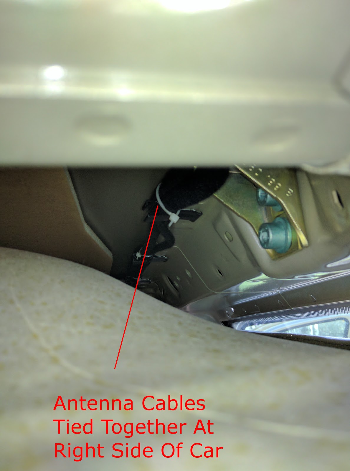
Routing the cable through the passenger side was rather easy, used cable ties to tie it to the normal antenna cable and through the A pillar.
Once down to the dash, I routed the cables above the blower fan where other cables were also routed.
Then to left from the blower motor to the 2DIN slot
You will then route the cables into the 2DIN slot, you must also remember to cut a small piece of the plastic, otherwise the radio will not fit. Although C500 is only 150mm deep, it still won't fit completely without this change. Because once the antenna connectors are installed, radio becomes 4-5mm thicker and connectors exactly sit at where the plastic support beam is.
Then you do the reverse when putting back all the dome lights, pillar panels and other covers.

Wednesday, May 24, 2017

Easy OpenVPN server setup for personal use

If you need VPN to access to resources at your home/work network. This is quite easy to accomplish using OpenVPN. Many times people over-do OpenVPN installations. It is not such a big task after all. You can simply use a single client certificate and username/password authentication. Therefore you won't need to deal with creating certificates per client. It is much nicer to use passwords because of simplicity, you can use the same client ovpn file for all the clients. While you can restrict access by using separate username/password pairs

Notice that in this setup, only the traffic targeted for the network behind the VPN server (defined by `push route` in `server.conf`) will be sent over OpenVPN connection. The normal traffic will use the normal connection. This further simplifies the process because you do not have to deal with NAT setups etc. for accessing internet while connected to VPN and you will get fastest direct Internet access while connected to VPN server.

You will need to open/forward port UDP port 1194 to be able to connect to your server.

Step 1

Install OpenVPN server and `easy-rsa` packages. (these are `openvpn` and `easy-rsa` on Ubuntu)


Step 2

Execute the following commands. You can use defaults for all the fields. You will only need to say `y` for signing the certificates. The `easy-rsa` path is from Ubuntu package. You may need to adjust your paths accordingly. (Note: The # sign means you need to be "root" user when executing these commands)
# cd /etc/openvpn
# cp /usr/share/easy-rsa/* .
# . ./vars
# ./clean-all
# ./build-ca
# ./build-key-server server
# ./build-key client1
# openvpn --genkey --secret keys/ta.key
# ./build-dh

Below is a full output of the commands when executed as an example:
# cd /etc/openvpn
# cp /usr/share/easy-rsa/* .
# . ./vars
NOTE: If you run ./clean-all, I will be doing a rm -rf on /home/eyurtese/openvpn/keys
# ./clean-all
# ./build-ca
Generating a 2048 bit RSA private key
......................................+++
...............+++
writing new private key to 'ca.key'
-----
You are about to be asked to enter information that will be incorporated
into your certificate request.
What you are about to enter is what is called a Distinguished Name or a DN.
There are quite a few fields but you can leave some blank
For some fields there will be a default value,
If you enter '.', the field will be left blank.
-----
Country Name (2 letter code) [US]:
State or Province Name (full name) [CA]:
Locality Name (eg, city) [SanFrancisco]:
Organization Name (eg, company) [Fort-Funston]:
Organizational Unit Name (eg, section) [MyOrganizationalUnit]:
Common Name (eg, your name or your server's hostname) [Fort-Funston CA]:
Name [EasyRSA]:
Email Address [me@myhost.mydomain]:
# ./build-key-server server
Generating a 2048 bit RSA private key
...............................+++
.......................+++
writing new private key to 'server.key'
-----
You are about to be asked to enter information that will be incorporated
into your certificate request.
What you are about to enter is what is called a Distinguished Name or a DN.
There are quite a few fields but you can leave some blank
For some fields there will be a default value,
If you enter '.', the field will be left blank.
-----
Country Name (2 letter code) [US]:
State or Province Name (full name) [CA]:
Locality Name (eg, city) [SanFrancisco]:
Organization Name (eg, company) [Fort-Funston]:
Organizational Unit Name (eg, section) [MyOrganizationalUnit]:
Common Name (eg, your name or your server's hostname) [server]:
Name [EasyRSA]:
Email Address [me@myhost.mydomain]:

Please enter the following 'extra' attributes
to be sent with your certificate request
A challenge password []:
An optional company name []:
Using configuration from /home/eyurtese/openvpn/openssl-1.0.0.cnf
Check that the request matches the signature
Signature ok
The Subject's Distinguished Name is as follows
countryName           :PRINTABLE:'US'
stateOrProvinceName   :PRINTABLE:'CA'
localityName          :PRINTABLE:'SanFrancisco'
organizationName      :PRINTABLE:'Fort-Funston'
organizationalUnitName:PRINTABLE:'MyOrganizationalUnit'
commonName            :PRINTABLE:'server'
name                  :PRINTABLE:'EasyRSA'
emailAddress          :IA5STRING:'me@myhost.mydomain'
Certificate is to be certified until May 22 10:41:07 2027 GMT (3650 days)
Sign the certificate? [y/n]:y


1 out of 1 certificate requests certified, commit? [y/n]y
Write out database with 1 new entries
Data Base Updated
# ./build-key client1
Generating a 2048 bit RSA private key
.............+++
........................................+++
writing new private key to 'client1.key'
-----
You are about to be asked to enter information that will be incorporated
into your certificate request.
What you are about to enter is what is called a Distinguished Name or a DN.
There are quite a few fields but you can leave some blank
For some fields there will be a default value,
If you enter '.', the field will be left blank.
-----
Country Name (2 letter code) [US]:
State or Province Name (full name) [CA]:
Locality Name (eg, city) [SanFrancisco]:
Organization Name (eg, company) [Fort-Funston]:
Organizational Unit Name (eg, section) [MyOrganizationalUnit]:
Common Name (eg, your name or your server's hostname) [client1]:
Name [EasyRSA]:
Email Address [me@myhost.mydomain]:

Please enter the following 'extra' attributes
to be sent with your certificate request
A challenge password []:
An optional company name []:
Using configuration from /home/eyurtese/openvpn/openssl-1.0.0.cnf
Check that the request matches the signature
Signature ok
The Subject's Distinguished Name is as follows
countryName           :PRINTABLE:'US'
stateOrProvinceName   :PRINTABLE:'CA'
localityName          :PRINTABLE:'SanFrancisco'
organizationName      :PRINTABLE:'Fort-Funston'
organizationalUnitName:PRINTABLE:'MyOrganizationalUnit'
commonName            :PRINTABLE:'client1'
name                  :PRINTABLE:'EasyRSA'
emailAddress          :IA5STRING:'me@myhost.mydomain'
Certificate is to be certified until May 22 10:41:47 2027 GMT (3650 days)
Sign the certificate? [y/n]:y


1 out of 1 certificate requests certified, commit? [y/n]y
Write out database with 1 new entries
Data Base Updated
# openvpn --genkey --secret keys/ta.key
# ./build-dh
Generating DH parameters, 2048 bit long safe prime, generator 2
This is going to take a long time
..................................+................................................................................................................................................................................................................................+................................................+.......................................................................+..............+......................................................................................................................+........................................................................................................+................................................................................................+.................+........................+...............................................................+...............................................................................+.................................................+.................................................................................................+.............................................+..............................................................................................................................................................................................................................+.....................................................................................................................................................................................................................................................................................................................+..............................................................................................+.....................................................................................................................................................................................................................................................................................................+................................................................................................................................+..........................................................................................................................+..........................+....................................................+............................................................+........................................................................................+................................+.............................................................................+............................................................+................................................................+................................................................................................................................................................................................................................................................................................................+..............+........................+.........................+........................................+.............................................................................................................................................................+........................................................+...............................................................................................................+........................+....................................................+.............................+....................................+.........................................................................+......................................................................................................................................................................................++*++*
Step 3

Create the OpenVPN server conf file at `/etc/openvpn/server.conf`. The `push route` command tells the server to push a route to client. In this setup only the pushed route is accessed through the VPN.


port 1194
proto udp
dev tun
ca keys/ca.crt
cert keys/server.crt
key keys/server.key
dh keys/dh2048.pem
server 10.8.0.0 255.255.255.0
ifconfig-pool-persist ipp.txt
# CHANGE TO YOUR HOME NETWORK BLOCK!
push "route 192.168.0.0 255.255.255.0"
keepalive 10 120
cipher AES-256-CBC
max-clients 100
user nobody
group nogroup
persist-key
persist-tun
status openvpn-status.log
verb 3
tls-auth keys/ta.key 0
client-cert-not-required
script-security 3
auth-user-pass-verify /etc/openvpn/checkpass.sh via-env

Step 4

Create client .ovpn file. The client program will ask username and password. The .ovpn file holds the client configuration and you will use it when connecting to the server. Clients with GUI often has an option to import the .ovpn file.

client
dev tun
remote YOUR_HOST_NAME 1194 udp
auth-user-pass
fast-io
float
explicit-exit-notify
cipher AES-256-CBC
remote-cert-tls server

PUT (COPY/PASTE) CONTENTS OF keys/ca.crt HERE


PUT (COPY/PASTE) CONTENTS OF keys/client.key HERE


PUT (COPY/PASTE) CONTENTS OF keys/client1.crt HERE


PUT (COPY/PASTE) CONTENTS OF keys/ta.key HERE

key-direction 1

Step 5

Create a password checking script at `/etc/openvpn/checkpass.sh` this is a simple script which uses plaintext passwords. You have to make sure to give execute permission to the script, eg. 755, otherwise OpenVPN server would not start. Using plaintext passwords is not a problem as long as you have the password file secure on your openvpn server. The OpenVPN authentication still uses encryption.

#!/bin/bash
# :mode=shellscript
#
# Gets environment from OpenVPN and checks user:pass from file

# set > /tmp/auth-user.env

LINE=`grep ${username} /etc/openvpn/userpass.txt`
IFS=: read user pass <<< ${LINE}

if [ "${password}" == "${pass}" ]; then
  exit 0
else
  exit 1
fi


Step 6

Create the actual passwords file at `/etc/openvpn/userpass.txt` and set its owner as `nobody:nogroup` and permissions as 600. You need to define your own usernames and passwords

username1:password1inClearText
username2:password2inClearText
username3:password3inClearText