Friday, May 24, 2019

VW Golf MK4 Rear Wiper Washer Jet Nozzle Pipe Repair

The rear wiper nozzle was rotating with the wiper arm. I had to open and see what was going on. Apparently the o-ring was broken and stuck between the washer jet pipe and the wiper pipe.

Luckily I checked the issue fairly quickly before it developed a worse problem. In many cases people realize this when the washer jet pipe is broken due to friction as it is not centered anymore without the o-ring. This causes washer fluid to leak inside the rear hatch and break latch microswitch and other things.

There is a repair kit for this purpose with part number 8L0 998 711. But it is as expensive as new motor and also fits only Valeo model as the washer jet pipe is slightly different in Bosch.

 
So, it is best to repair it before it develops a worse problem. Below is a picture of the repair kit but I did NOT use it. But it comes with 1 small o-ring and 2 large o-rings (one is not visible in the picture as it is on the wiper arm shaft already.). I don't know if the large o-rings are same size as the front wiper arm shaft o-rings. But it looks like they are probably same size.


Dissassembly And Re-assembly

Luckily there are only 2 screws and 1 panel to remove to reach the wiper motor. In this Golf MK4 Estate / Variant model. The screws are inside the handles for closing the rear hatch. (philips head screws)

Once the screws are opened, the panel can be removed by pulling out. Use some plastic opening tools and start from the middle and be patient. It is easy to break the plastic pieces on this panel, if panel is removed unevenly (eg. one side pops out with force), as the clips are really tight.

Once the panel is removed, you can access the motor. The only thing to do is to remove the electrical connector by opening the latches using a small flathead screwdriver and the washer fluid pipe by pulling out.

Normally, once the small torx screws are removed. The rear panel should come off quite easily. In my case it was very difficult to pull it out as the o-ring was stuck between pipes and it was very difficult to pull it out. I had to use some flathead screwdrivers to pry it slowly out while turning around.

Above is a picture where the pipe is partially out. Once it goes off a little bit, it is possible to remove the rear plate.
Once it is removed, and it is in good condition. You only need to clean inside the wiper arm pipe before re-installation.

I found pieces of the small o-ring inside the wiper arm pipe. The washer fluid pipe outer diameter is 3.4mm and the wiper arm pipe inner diameter is 4.7mm. I found some 3mm inner diameter (I.D.) and 1mm thickness (C.S.) o-rings from AliExpress and it seemed to be exactly same as the original. So this makes 5mm outer diameter so it fits quite snugly.

I only had half of the original o-ring but I measured it was slightly thinner than the new o-ring. Perhaps years of usage may have thinned it a bit. But when I put them on top of each other, the curve matched perfectly.


As I pulled the inner pipe quite a bit when removing. It seems like it moved a bit out from it's plastic holder. I had to warm it up using hair drier and hammer it back in gently.

As you can see, it fit slightly too long before hammering it. It should normally be flush with the outer pipe.

Here is a picture I took when inserting the o-ring in place. I simply put it on top and push it down using the washer jet nozzle. Yes, it is swimming in bearing grease.

The installation is reverse of removal. It appears there fits 2 o-rings (3 o-rings is about 0.5mm too much!). So I pushed in two o-rings so it is now double sealed. Perhaps better than new?

There is another o-ring which is on the wiper arm shaft but I did not remove it. Perhaps it would be wise to check it also once in a while.


Monday, May 20, 2019

Epson Expression Premium Waste Ink Pad Replacement / Cleaning

Many expression premium printers have similar waste ink pads. Epson has 2 part numbers. First one is 1612118 and the second one is 1611102. You can always use the 1611102 in your replacements. They are often the same price and 1611102 has larger capacity.

Why Epson has two different parts? That is a matter of pricing. The smaller waste ink pad will be filled quicker and you will need to replace your printer more often. Epson has the smaller type in cheaper models, such as XP-540. At least mine had the smaller type.

Removing Waste Ink Pad Container

First you have to start by removing the two black screws holding a plastic trimpiece.
After that, you can simply lift it up and remove. You will gain access to two silver screws under it. Unfortunately I forgot to take picture of them :) The one on the right is deep inside the device so you may want to use a magnetic screwdriver head or a magnetic pickup tool.
After removing the plastic piece, you will gain access to one more screw. One was already visible. You may need to remove the paper tray completely to see it.
In this printer all the visible screws are black and others are silver colored. Once you remove these screws, you can also remove the lower cover piece.

You will gain access to one more silver screw. This screw and one under the device holds the waste ink pad container in place. The screw under the printer is shorter.
You may tilt the printer when doing this. However, ink may leak if container is too full. It should not be too full. But you never know.

The safer way is to put the printer on top a straight table and leave the container outside the table. As you can see, printer's legs are inside anyway.

You need a screwdriver to lift the plastic slightly to be able to pull the ink container down. Once the container is removed, you can clearly see the ink outlet.

Cleaning or Changing The Sponge

Normally all you need is to dry the sponges. Once they are dry, they should be able to absorb nearly as much liquid as they did originally. But you can also wash them.

One important thing to remember is to not give in to temptation of squeezing them. They will be flattened and won't work as well anymore.

The best way to clean them is simply putting them under running water until no ink comes out.

You can then dry the sponges on a heater or let them dry out outside etc. Make sure to not leave them on a surface which may absorb the ink. Because there comes out small amounts of ink even after through rinsing.

The installation is reverse of removal :) Here is the end result.

How Much Liquid Was Inside?

When I removed the ink container, first thing I did was to measure it's weight.
It weighted 148.2g then I weighted the container with washed, rinsed and dried pads again.
The weight is 61.6g. This tells me that the container was holding ~85g of liqud.

Some Experiments

I wanted to figure out if I could replace the pads with another material. The most logical choice was "magic sponge". It is super absorbent and easy to cut into shape.


 It was easy to install them to place.

The original sponge was 3.5cm high. But I used even smaller 3cm high magic sponge setting in my experiment.

First the dry weight. It was 57.2g
I have first filled the container with water, then turned it upside down until it stopped dripping. This way I could estimate how much liquid the sponge could absorb.

Wet weight 153.9g. So it managed to absorb ~95g easily. That is a pretty decent result considering I used a smaller piece of sponge.

By the way, you can literally buy 100 pieces of 10 x 6 x 2 cm sized magic sponge for less than 5euro! The container has six ~1cm thick pieces so you can use 3 sponges for 1 refill!

Below is outline of the pads (not to scale!) the last piece in the drawing is the middle part which has 3 of same pieces. Total number of pieces is 6.


The height of the smaller waste ink pad is 33mm and the container holds up to 58mm safely.

Saturday, May 4, 2019

Epson 33 / 33XL Cartridge Anatomy and Refilling

Most older cartridges have strange airways and passages in them. In some ways perhaps to justify filling cartridges half full. New Epson cartridges are smaller and they do seem to have a more straightforward construction.

It is possible to carefully cut open an Epson cartridge without damaging it. One side of the cartridge is airtight and this is the side which is opened in picture below. The other side simply has another wall under it.


As can be seen easily, the cartridge has a single main chamber. There is a tight canal where the ink outlet is.

The air inlet port is very tight. The cartridge is able to keep vacuum inside. It looks like the inside volume of the cartridge is designed to shrink as the ink is used. The metal plate in middle and the spring under it ensures that inside the cartridge is always negative pressure so the ink will not flow out.

If the inside volume nears zero. The metal plate presses to a lever which opens the air inlet port in corner until it gets in some air so the negative pressure will not rise beyond a level.

I have found out that the cartridge keeps negative pressure even if it has no liquids. There must be some mechanism or membrane at the ink outlet which does not allow air or liquids to travel towards inside the cartridge.

As can be seen below, cartridge keeps the foil completely pressed in with very little volume left inside. It does NOT replenish missing content with air. The air intake valve does not allow air intake even though the spring inside the cartridge is creating negative pressure.


Refilling Epson 33 / 33XL Cartridge


Unknown to most, the green cartridge caps do not make an airtight seal around the outlet port.


The cap will tighten the bottom of the cartridge perfectly. However the little pipe in front of the cartridge outlet is connected to the inside of the cartridge.

As can be seen clearly, the pipe is connected to space between the side wall and transparent foil. The side wall has a labyrinth and a hole to outside. The labyrinth is probably to keep the dust outside. I also found out that some cartridge walls are not completely sealed at factory as I have seen them leak at arbitrary points!

This means that you can't simply make a hole anywhere on the cartridge for filling. As even with the green cap installed, the cartridge will start leaking to inside immediately as there will be no negative pressure holding the ink. The ink will flow out from the outlet and enter to the pipe. It will then travel between the transparent plastic piece and the black wall with air hole.

Before I found out about this, I have drilled few cartridges from the top and tried to fill them. The result was that the ink eventually started coming out from the side wall hole. In some cartridges the wall was not totally sealed so it started seeping through the

Refilling Option 1


As the ink will flow out from cartridge if the negative pressure is stopped. We may only fill the cartridge from bottom. The only suitable place I found for this purpose is the prism eyelet.

You must drill the eyelet very carefully as it is only 2mm away from the plastic foil. I found out that eyelet gets drilled very quickly so do not apply any pressure to the drill.

Yes, the plug covers the eyelet hole but printer simply will think that there is ink. It is possible to put the flap other way around also. I felt little resistance first but cutting the little part of the wall solved the issue. Perhaps you may find smaller plugs also.


Even the ink must obey the laws of gravity. So it won't be leaking out from the output port when it is the highest point.

However, when plugging the hole, you must squeeze the cartridge from sides to expel as much air as possible. This way once you release the cartridge, there will be little negative pressure built inside it.

Refilling Option 2


So you prefer having a hole on top? That is also possible. As usual, you need to drill very carefully as within 2mm distance is the transparent plastic cover. Just use patience and do not press the drill down at all. Let it slowly form the hole.

As the air pressure balance pipe in the outlet is the problem. We can simply block it so the ink won't be able to flow down when the inside negative pressure is lost. You can simply put a small piece of silicone sealant using a toothpick to the hole.


Yes, it would perhaps be possible to re-open the hole after filling using a needle. But what happens if we don't? Perhaps ink flows more rapidly down due to negative pressure built when it is used by the ink head? I have left the hole plugged and did not see any negative consequences yet. Actually, none of the chinese cartridges have such hole either. I am not sure what worst can happen.

Then you need to make the hole in the middle of the cartridge where the other side is connected to top solidly.


Once the green cap is on, the ink will not be able to flow down due to pressure build up at the outlet. However, you still need to squeeze cartridge when inserting the plug. So once you relese it, there will be slight negative pressure built inside the cartridge. Without any negative pressure, cartridge may leak until pressure is balanced, once the green cap is removed.

One thing to consider is that in this position the plug interferes with the metal plate inside the cartridge. However it is probably not a problem. This can be seen in my very first picture which I took from the side of the cartridge.

Monday, April 29, 2019

WAGO vs Other Brand Terminal Connectors (namely VSELE)

WAGO terminal connectors are very well known worldwide. They can be quickly tightened and loosened without requiring any tools.  Unlike cheaper screw connectors, in most cases will not damage the wires when the terminal is tightened.

After intensive advertising and product introduction campaigns WAGO is probably the world leader in this type of terminal connectors. As many other expensive product producers there is wide assumption of superfluously high quality and cheaper products will burn your house down.

Is there really significant quality difference to warrant paying up to 2x-3x more per connector? The cost of the VSELE connector is about 7€ for 60 pieces and 100€ for 1000 pieces amounting to 10cents per piece!


So the WAGO connector was rated for 20A 300V and 3rd party connector was rated for 32A 400V (specifications can be accessed here). In reality this connector is a copy of WAGO 222-412 model.

Perhaps it is comparing apples and oranges. But I do not have access to WAGO 222-412 and VSELE does not seem to produce the smaller model. I will try to update the article if I can get a genuine WAGO 222-412 model.

Physical Appearance

The WAGO terminal connectors is significantly smaller in size. Perhaps a plus point if you are working at very tight spaces. However it seems to come at a cost as the walls are thinner. The competitor's part is significantly thicker and sturdy looking.

WAGO seems to be optimizing material savings. Perhaps for reducing costs. The less material used per connector will translate into cheaper production costs.

For example the competitor's wire holes are round while WAGO item trimmed it down to square saving materials. I have never seen square wire so I can't imagine why else the wire entrance hole would be square.

Heat Resistance


While WAGO did not mark the material used in the connector. The competitor's connector was marked PA66.

I made a naive test on the connectors by heating them up to ~100C then to ~150C. At ~100C I observed no change however at ~150C both connectors deformed.

In addition, both connector materials formed bubbles inside while the competitor's connector had more bubbles. This may be due to difference of thickness of the materials used.

Material Quality and Rust Resistance


After the heat test, it was impossible to operate the connectors anymore. Both were fused together. I could break into the casing of the WAGO terminal connector easily using pliers. However the competitor's product was simply too tough for pliers. I needed to use a rotary tool to cut into it and even then it was quite difficult. Perhaps this is where the thickness help.

I have submerged both connectors into white vinegar and the metal parts on both seemed to survive. However WAGO developed an oxidation layer. Below is a picture taken after a day of submerging.


On left is WAGO where the white surface can be seen on the conductive material. On the right is the VSELE connector which seems uneffected.

Conductive Surfaces


Both connectors use internal latches to catch the wires. It looked like WAGO connector seem to align the internal latch so it will be angled to make it harder to remove the wire by pulling. While the competitor's latch dropped down straight on top of the wire.

The WAGO conductive surface was 0.5mm thick and the competitor used 0.8mm thick surface. The thicker conductive material will allow higher currents to pass. Perhaps in this case the reason was that the competitor's product was rated for higher current, although still cheaper than WAGO.

One difference in construction was that WAGO simply rely on the plastic pieces to keep the latch in place. So latch came out when the plastic was broken, potentially releasing the wires. While the competitor's latch was making a loop around the conductive surface then get back to push the wire down on it. So, it was operable even after breaking the plastic case into pieces.

Table of Differences


WAGO VSE-412
Size Smaller size - Smaller size may be beneficial
Heat Same Same Similar resistance to heat
Metal Quality - Resistant to corrosion Resistance to corrosion will allow better conductivity in the long run
Build Quality Same Same Similar build quality
Conductivity - Thicker material Thicker conductor will transfer larger current with less resistance
Latch - Stronger mechanism Stronger mechanism will keep wires attached in unlikely failure of the plastics

Conclusion


Perhaps there can be very poor quality chinese replicas of these connectors. However it would be unfair to judge the most expensive product on the market with the cheapest to draw a general conclusion.

Of course the sellers will try to sell you the most expensive product. Because most companies add a percent profit to their purchase price. This simply means more expensive product means more profit. In addition, expensive products are easier to replace in case of failures as the product price is so high to cover multiple replacements per item.

It looks like VSELE's connectors are high quality and much cheaper. So why not give them a try in your next purchase? VSELE says on their page "The comprehensive product line has more than 1000 models which have been approved by TUV, CE, CQC, SGS, ROHS,SASO. the products sells well to UK、Spain、Portugal、Singapore、Turkey、Russia、 Korea,South Africa…… more than 70 countries and regions."

Tuesday, March 26, 2019

Using Mac OSX High Sierra with VirtalBox on an AMD FX-8350 processor

I recently needed Mac OSX to be able to downgrade my printer firmware. I tried to install MacOSX on VirtualBox but it was not a very straightforward procedure.

I have followed the instructions, and downloaded the disk image from here: https://forum.amd-osx.com/viewtopic.php?t=4029

Then I needed to create a virtual machine within virtualbox. Using default options for Mac OSX High Sierra and downloaded disk file as the main drive.

I needed to modify some of the settings before things started to take shape.I did not use all the modifications within the instructions. Only the following seems to be doing the job pretty good.

cd "C:\Program Files\Oracle\VirtualBox\"
VBoxManage setextradata "Mac OS X High Sierra" "VBoxInternal/Devices/smc/0/Config/DeviceKey" "ourhardworkbythesewordsguardedpleasedontsteal(c)AppleComputerInc"
VBoxManage setextradata "Mac OS X High Sierra" "VBoxInternal/Devices/smc/0/Config/GetKeyFromRealSMC" 1
VBoxManage setextradata "Mac OS X High Sierra" VBoxInternal2/EfiGraphicsResolution 1920x1080
VBoxManage setextradata "Mac OS X High Sierra" "VBoxInternal/Devices/efi/0/LUN#0/Config/PermanentSave" 1
VBoxManage modifyvm "Mac OS X High Sierra" --cpu-profile "Intel Xeon X5482 3.20GHz"


The graphics card memory can stay at 16MB and setting it higher does not seem to effect anything. However I had to uncheck the "Enable Nested VT-x/AMD-V" setting at processor tab in settings.

Only after these settings it was possible to boot the image. I could not install the upgrade without the cpu-profile option set. I had to use a different resolution due to my display size. The VirtualBox was setting a different default size.

Wednesday, March 13, 2019

Upgrading Ubuntu 17.10 with PostgreSQL 9.6/PostGIS 2.3 to Ubuntu 18.04 LTS PostgreSQL10/PostGIS 2.4

After upgrading to 18.04 Bionic, you will receive an error if you try to upgrade PostgreSQL 9.6 database which use PostGIS 2.3 which is the default versions in Ubuntu 17.10 Artful. You will receive an error message in loadable_libraries.txt error file when running pg_upgradecluster -m upgrade 9.6 main

could not load library "$libdir/postgis-2.3": ERROR:  could not access file "$libdir/postgis-2.3": No such file or directory
could not load library "$libdir/rtpostgis-2.3": ERROR:  could not access file "$libdir/rtpostgis-2.3": No such file or directory

The problem is due to PostgreSQL 9.6 does not have PostGIS 2.4 library installed and PostgreSQL 10 not having support library for PostGIS 2.3. So the upgrade is impossible with their infinite wisdom, Ubuntu 18.04 does not provide PostGIS 2.3 for PostgreSQL 9.6.

To be able to overcome this problem you will need to install necessary libraries which produce an upgrade path from PostGIS 2.3 to PostGIS 2.4. Eg. both 2.3 and 2.4 libraries should be installed for the PostgreSQL 9.6 or 10.

However there is no postgresql-9.6-postgis-2.4 package for Ubuntu 17.10 and installing the 18.04 package will yield an error as seen below.

# dpkg -i postgresql-9.6-postgis-2.4_2.4.4+dfsg-4.pgdg18.04+1_amd64.deb 
Selecting previously unselected package postgresql-9.6-postgis-2.4.
(Reading database ... 177473 files and directories currently installed.)
Preparing to unpack postgresql-9.6-postgis-2.4_2.4.4+dfsg-4.pgdg18.04+1_amd64.deb ...
Unpacking postgresql-9.6-postgis-2.4 (2.4.4+dfsg-4.pgdg18.04+1) ...
dpkg: dependency problems prevent configuration of postgresql-9.6-postgis-2.4:
 postgresql-9.6-postgis-2.4 depends on libgeos-c1v5 (>= 3.6.0); however:
  Version of libgeos-c1v5 on system is 3.5.1-3.
 postgresql-9.6-postgis-2.4 depends on liblwgeom-2.4-0 (>= 2.4.0~rc1); however:
  Package liblwgeom-2.4-0 is not installed.
 postgresql-9.6-postgis-2.4 depends on libprotobuf-c1 (>= 1.0.1); however:
  Package libprotobuf-c1 is not installed.

dpkg: error processing package postgresql-9.6-postgis-2.4 (--install):
 dependency problems - leaving unconfigured
Errors were encountered while processing:
 postgresql-9.6-postgis-2.4

The package gets installed never the less. If you have tried to install postgresql-9.6-postgis-2.4 on Ubuntu 17.10 then you will need to remove it before upgrading to Ubuntu 18.04 Bionic or the upgrade will fail. So remove it before continuing.

# dpkg -r postgresql-9.6-postgis-2.4
(Reading database ... 177501 files and directories currently installed.)
Removing postgresql-9.6-postgis-2.4 (2.4.4+dfsg-4.pgdg18.04+1) ...


Also there is no postgresql-10-postgis-2.3 package available in Ubuntu 18.04 Bionic.

Upgrade Solution 1


Do not use -m upgrade , you can simply use pg_upgradecluster 9.6 main However this will dump the database and import it and it may take very long time with large databases.

Upgrade Solution 2


Luckily there is a postgresql-9.6-postgis-2.4 package available for Ubuntu 18.04. The solution is to first upgrade to Ubuntu 18.04 then install postgresql-9.6-postgis-2.4 package from PostgreSQL PPA and upgrade the 9.6 database first.

There are two ways to install the required packages. First way is to add the PostgreSQL PPA to your system using the instructions at PostgreSQL Ubuntu download site. However if you do this, you will end up upgrading to PostgreSQL packages provided from the PostgreSQL PPA in your next upgrade. If you want to stick with Ubuntu provided packages, you should either not do this or remove the PPA after installation of required packages.

The second way is downloading the .deb packages directly from PostgreSQL site. It is possible to get a listing of all the packages at the PostgreSQL PostGIS APT download site. I simply downloaded the .deb file for this process

You can install the .deb file and then you will need to copy the upgrade path sql file to PostgreSQL 9.6 folder.  (as root)

# dpkg -i postgresql-9.6-postgis-2.4_2.4.4+dfsg-4.pgdg18.04+1_amd64.deb
# cp /usr/share/postgresql/10/extension/postgis--2.3.3--2.4.3.sql /usr/share/postgresql/9.6/extension/postgis--2.3.3--2.4.3.sql

After the installation become postgres user and connect to databases which use the postgis extension using psql and update it to 2.4.3.

# ALTER EXTENSION postgis UPDATE;
NOTICE:  version "2.3.3" of extension "postgis" is already installed
ALTER EXTENSION
# ALTER EXTENSION postgis UPDATE TO '2.4.3';
WARNING:  'postgis.backend' is already set and cannot be changed until you reconnect
WARNING:  'postgis.gdal_datapath' is already set and cannot be changed until you reconnect
WARNING:  'postgis.gdal_enabled_drivers' is already set and cannot be changed until you reconnect
WARNING:  'postgis.enable_outdb_rasters' is already set and cannot be changed until you reconnect
ALTER EXTENSION

After that you should be able to run pg_upgradecluster -m upgrade 9.6 main without any troubles.

After Upgrade


After the upgrade, if everything is working. You can remove the PostgreSQL 9.6 cluster and you can also remove all other packages related to PostgreSQL 9.6.

Friday, January 11, 2019

VW MK4 Door Microswitch Replacement

The switch which check if a door is open or not resides inside the door lock module and sometimes it gets broken. Mine stopped working and I was forced to investigate the issue. When this happens, the vehicle does not recognize the door is opened. Eg. there won't be dash warning and the interior lights will not come on when the door is opened.

There are many tutorials on removing the door cart and the panel to reach the door lock. So I will skip those steps.

The Switch And The Problem

Switch is near the bottom of the unit and can easily be traced as blue/red wires go to it.

There are several ways the switch is broken. Sometimes the plunger goes off or the rubber seal breaks down and corrodes inside the switch.

In my case it looked like switch was somehow swollen a little bit and maybe the metal pieces of the lock was slightly deformed. As such, the plunger was not under the lock piece which should press it down. When the switch is half way out, the lock piece is not able to push it down. As can be seen below.


The white part is the seal and black round piece on top is the plunger. It is suppose to be pressed down by the black lock piece but switch is half way out of position.

Whatever the reason, the best solution is to change the switch. There are few types of the switch and few different ways it is installed. Older locks have melted tabs which keep the switch in position where newer locks have latches which allow switch to be removed.

Also there are repair kits. For me the right door switch kit code was 3BD 998 786. I obtained a replacement switch from AliExpress. This switch was the latest model which has a metal piece to support the plunger and increase contact area!

3BD 998 786 comes with crimp butt connectors which allow you to cut the wires and reconnect. However I did not use them.

Seperating Electrical And Mechanical Parts

Lock unit has 2 parts. One part houses all the mechanical parts and other part has microswitches, motor etc. First we must separate these to be able to access the solder points of the red/blue microswitch wires.

First remove the microswitch from the mechanical part. It could be in place by plastic tabs, metal retainer or plastic latches.

Then, you need to remove 2 screws and pull the outside door handle latch completely open. Below are these marked with red arrows.


After removing the screws, you need to pull the door handle latch completely and keep it open.


Now you can wiggle the pieces and separate them.

Removing Circuit Board

The circuit board is inside the plastic box. You need to remove the torx screws around it. There are 9 screws to remove. After this, you can pry open the box. It may feel like it is glued due to the seal inside. However,  you can slowly open it.

Make sure to separate the pieces slowly so parts will not fall out.

Desoldering And Resoldering Wires

The circuit board is covered with some sort of resin for moisture protection. That is why the board and solder joints looks dark/red in the photos.

First settle the board carefully using helping hands.


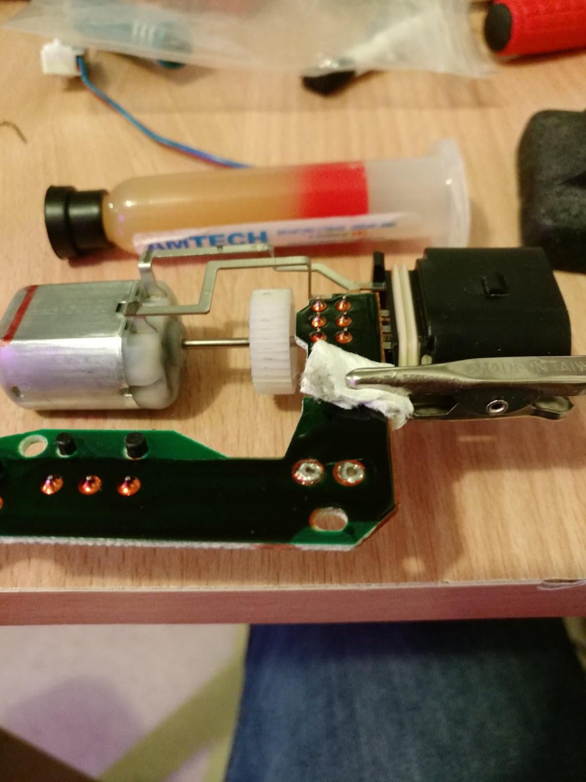
Now you can melt the solder and pull the wires out.


Once the wires are removed, clean the surrounding area first. Then, you can put the replacement part's wires in place and also use flux for a good connection.


Once the connection is made, you should re-coat the circuit. You can use any kind of non-conductive lacquer for water proofing. But best is to use some sort of conformal coating. I used plastic spray for electronics boards.


Simply, I first masked the area and then sprayed over it. It should be good enough for a while.

Reassembling The Lock

Reassembling the lock is simply reverse of the disassembly. You need to re-attach the microswitch to mechanical piece using the same method as original switch was assembled. Mine used melted tabs, so I had to use plastic weld glue to create tab pieces on top.

Final Result

The switch with the metal helper sits so much better in place and I expect it to work for many years to come. You can see the difference below at door locked and opened positions.

Door locked:

Door opened:


Clearly the new type switch works so much better compared to the older type.