
I have recently retrofitted a VW Golf MK4 Variant 2002 with a new triplex antenna and deployed cables for it. It was a tedious slow moving project because it is not even possible to find the right cable lengths needed and had to collect many parts from different sources and modify them.
Step 1 - Obtaining an Android head unit
Obtain a good Android car head unit. I have obtained Ownice C500 unit. With 150mm depth, it barely fits to the 2DIN slot available on MK4 Golf. I would advise against any radio which is deeper than 150mm. IF you do, you would need to cut some plastic parts behind the 2DIN slot.Step 2 - Obtaining necessary items
Obtain the necessary cables and tools. Hopefully I did not forget to list something. You will need:| Amount | Item |
| 1 | 4+m LMR-195 (or RG-58) for GSM/3G/LTE |
| 1 | 4+m LMR-100 (or RG-174) for GPS |
| 1 | 3+m RG178 for microphone |
| 1 | 2DIN Golf MK4 Plastic Frame/Fascia (CT24VW08) |
| 1 | RNS/RCD microphone holder for VW Golf |
| 1 | Triplex antenna 1J0 045 498 C (changes depending on your region) |
| 1 | VW antenna phantom power adapter |
| 1 | ISO harness |
| 1 | 3.5mm mono microphone jack |
| 1 | OBD female plug (optional) |
| 1 | USB OBD with FTDI or Prolific chipset (optional) |
| 1 | 12v relay (optional) |
| 1 | FMA Female to SMA Male adapter |
| 1 | RAST II 2 female onnector for LMR-195/RG-58 |
| 2 | SMA male 90 degree crimp connectors (for RG-58 and RG-174) |
| 1 | Coaxial cable cutting tool |
| 1 | Crimp tool for coaxial cables |
| X | Harness tape |
| X | Cable ties |
| X | Some 2pin connectors (optional) |
For the microphone the actual needed cable length is 2.5m and for antenna it is 4m.
The space for cables in passenger side A pillar is limited. I could fit one 5mm diameter (4G) and two 2.5mm diameter (MIC + GPS) cables only.
The GPS antenna has an built-in amplifier so you can get away with using the thinner cable such as RG-174 however I recommend using LMR-195 for the 4G connection.
I used RG178 for the microphone cable, because I bought a cheap chinese RNS/RCD microphone for VW and it came with unshielded cable which caused strange problems and RG178 was the only shielded cable I had at that moment. You can use any microphone cable which has similar diameter.
The reason for the 90 degree angle SMA male crimp connectors is the length of the 2DIN slot in VW Golf MK4. If the connectors are straight, the radio does not fit anymore. You will still need to cut a small piece of the plastic there because the head unit stays few mm outside otherwise.
I used 1J0 045 498 C with green circle at antenna connector. I read this was for EU region in a forum post. But I do not know if this is true or not, all I can say is that it works fine.
Step 3 - Fitting the head unit into a frame
Because this specific universal model has some strange size issues. It was very difficult to fit it into any frame/fascia. You can forget about metal fascias because the plastic pieces on the sides make it impossible. Also the best fascia I found was a plastic one. The best fitting one is called with model CT24VW08 at some places.

You will also need to grind the front window of the frame. Because the head unit display is slightly larger than the frame itself. Once you have the radio at hand, you can easily figure out how much to grind off.
Step 4 - Setting up the head unit harness
VW Golf MK4 uses standard ISO harness. Universal C500 comes with a connector with a bunch of open wires. You will need to buy an ISO harness and connect the wires together.
A1  -  GALA (Speed Pulse)
A2  -  Not Connected
A3  -  ISO-9141-2 K-Line
A4  -  +12V Switched
A5  -  +12V Battery
A6  -  Illumination
A7  -  +12V Battery
A8  -  Ground
What we need to do is to make a little adjustment. There is a yellow plastic piece on the side of the connector. First we have to pull out the yellow plastic, then we can push back the pins. You will need a pin extractor or a very small flat head screwdriver.
Note: In MK4 harness the switched and permanent live wires are in wrong places and normally they should switch places. However when I made the radio harness, I made it MK4 compatible so I did not need to switch their places. It is up to you to figure out everything is connected to correct counterparts!
We need to remove A5 and put to A2. We will use the antenna power output from the head unit to power the built-in amplifier of the antenna. Normally A5 is the pin for antenna motor (out) eg. radio sends power to it when radio functionality is on only.
Normally the phantom power adapter comes with a suitable pin ready for installation as seen below (the blue wire). This should be connected to A5

A1  -  GALA (Speed Pulse)
A2  -  +12V Battery
A3  -  ISO-9141-2 K-Line
A4  -  +12V Switched
A5  -  Antenna Power (blue)
A6  -  Illumination
A7  -  +12V Battery
A8  -  Ground
12V Relay & OBD Support
Optionally, you can use the K-Line pin to access OBD using an OBD adapter. I have used a USB OBD adapter and I am able to access engine information realtime from my dash now. The relay I used only turns on the power to the USB adapter when the ignition is on accessory position. So no risk of emptying the battery unless you do it by leaving the key on accessory position.

You will also need power for this. I have used the spare power line from A2 and a 12V relay (a digital relay). I used a digital relay because I did not know how much load there can be on the switched power. With a digital relay, I am able to get away with 5mA usage when the relay is on, meanwhile a normal relay could have used over 200mA to power the coil.

Relay Input
DC+  -  +12V Battery from A2
DC-  -  Ground from A8
IN   -  +12V Switched from A4
Relay Output
NO   -  +12V output dor use with accessories
COM  -  DC+/+12V Battery using a jumper cable
NC   -  Not Connected
Now for the OBD connector the pins should be connected as follows:

4   -  Ground from ISO harness A8
7   -  ISO-9141-2 K-Line from ISO harness A3
16  -  +12V from relay NO output
The relay will turn on the power to OBD only when the key is in accessory position. So it will not drain the battery while the key is out.
You may use the power output from NO connector of the relay to power other items which need power, knowing that they will stop drawing power when you turn off the ignition and remove the key.
You need an OBD adapter with FTDI/Prolific chipset because these are the only chipsets supported by Android. I tried Torque Pro, however it seem to have a lot of problems with USB adapters. I would advise testing the connection using OBD Fusion.
Note: The original OBD connector just above the ash tray and this one can't work together. So you must be sure to close all OBD apps in the head unit when using the original OBD connector.
Microphone
First of all you must make sure that you have a dome light where you can install the microphone. Otherwise you may need to find out a dome light with microphone location or put the microphone at a separate location.

I bought a chinese RNS/RCD microphone for VW and it came with bad cable and bad microphone. Also it required phantom power for the circuitry


GPS/4G Signal Cables
I originally bought 5m SMA male to SMA female cables with LMR195 and RG174. (then I cut them to size)
I have installed the RAST2 female connector to LMR195 and I have tied it together with the SMA female ended RG174 cable with the cable loom tape. I did not need to change the SMA female part because I used FMA female to SMA male adapter for GPS. The head unit end of the cables should have 90 degree SMA male plugs.
Step 5 - Lowering the headliner for installing the cables and triplex antenna
You will need to lower the headliner for installation of the cables. This is not a very simple task because the car was built from top to bottom. So normally you would need to disassamble starting from bottom parts. However it is way too much work to remove everything only to put a wire. I have figured I can lower the headliner slightly and install the cable without removing everything. You may want to watch a few headliner removal videos for details.If you are wondering, why bother with this, because your GPS works fine inside the car from your phone etc. Then you should re-think, because I am getting 1m accuracy in GPS at all times while my phone can do 3m - 5m accuracy inside the car. It is a physics issue really, the metal rooftop of the car blocks some of the GPS signal and this will reduce accuracy. While at a perfect day you may get away with this, on a cloudy day with rain etc. you may find your GPS to be too unreliable. Same goes for GSM signals, they will be blocked by the metal parts of the car. So it is quite advantageous to use the VW antenna designed for the task.
I first removed the driver and passenger seatbelt parts from the B pillars. All you need is a 17mm wrench. Next you can start pulling out the panel near the rear hatch. Under it are 2 screws and a plastic clip to remove.
Now we are ready to pull out A, B, C and D pillar covers. They are all installed using plastic clips so you can loosen them simply by pulling. The A and D pillar covers are removed completely but you only need to open the upper end of B and C pillars.


You must also remove the interior lights, the rear seat lights are best removed by pulling out the side where the metal clip is. However if it is stuck, you must push the metal clip with a thin butter knife. You may break it if you force it. The front dome light has two screws holding it. You may want to watch some removal videos to understand how to remove them.
One tricky part to remove is the sunshade holding clip. The best way to remove it is to use a thin screwdriver to push the plastic from inside.

Step 6 - Installing triplex antenna and cables
One of the first things I made was to open the triplex antenna and check internals and seals. I have used Molykote 111 Compound in the antenna seals before I closed it back and also used silicone to cover the screw holes to protect the screws.

You simply remove the nut holding the old antenna and pull it up and put the new one in its place to replace it. As you can see below, there is already a plastic holder for the cables but they were not installed in my vehicle.

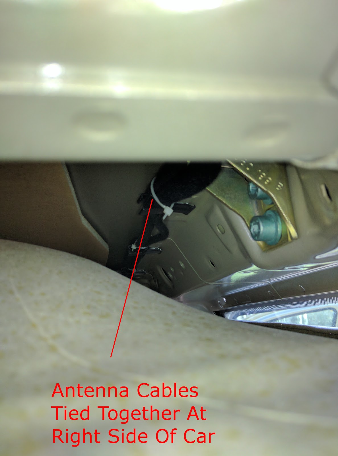
Routing the cable through the passenger side was rather easy, used cable ties to tie it to the normal antenna cable and through the A pillar.


thanks for details
ReplyDeleteI hope it was useful!
Delete